So it's been awhile since I started this thread about torque plates (aka honing plates) for our Dodge flathead sixes, but after more than a few delays (life gets in the way) I've finally got my machine shop equipped with large enough tools to press ahead with making a torque plate and answering my question.
To start, I purchased a 24" x 8" slab of 1" thick, hot rolled, low-carbon steel (1018 or A37 or similar) from a steel supply house to make the torque plate from. Ideally, I would have gone with cast iron, i.e. the same material as the cylinder head, but I didn't have an unusable cylinder head to carve up, and a slab of cast iron of the necessary dimensions is remarkably expensive. So steel will have to do, and frankly, I doubt that the material will make a significant difference in the results.
I set up the slab on a Cincinnati Cinova 80 horizontal mill with a vertical attachment, and a 3" diameter roughing shell mill, and trimmed the sides until the dimensions of the slab matched those of the original cylinder head. Then, using an 8" carbide insert face mill, one side of the slab was milled flat.
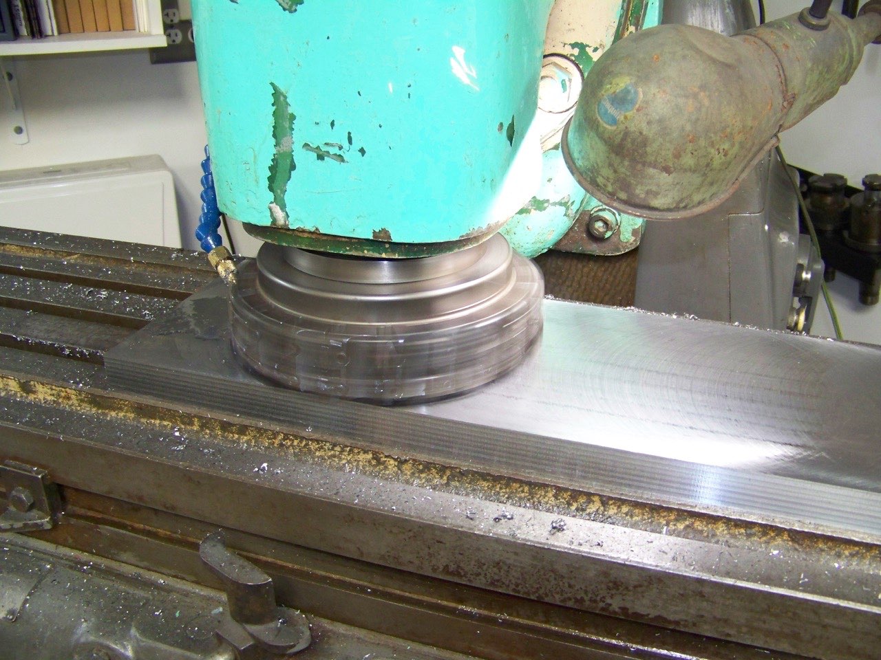
- 100_1550.jpg (250.18 KiB) Viewed 9060 times
After milling, the flatness was checked with a machinist's straight edge, and the variance across the opposing corners was less than 0.0015"; the manual allows up to 0.004" per foot of length.
Using some 7/16-14 transfer screws, I positioned the slab on the cylinder block, and marked the 21 holes for the cylinder head bolts. Once these holes were drilled and chamfered, I blued the machined face of the slab and bolted it to the block. Flipping the block upside down and reaching in through each cylinder bore, I scribed the inside diameter of each bore into the bluing. After removing the slab, the center point of each cylinder was scribed and center punched, and the cylinder holes were bored through the slab, using an adjustable boring head to finish the holes to a size large enough to allow for the maximum overbore (0.060") plus some room for the boring and honing tools if needed.
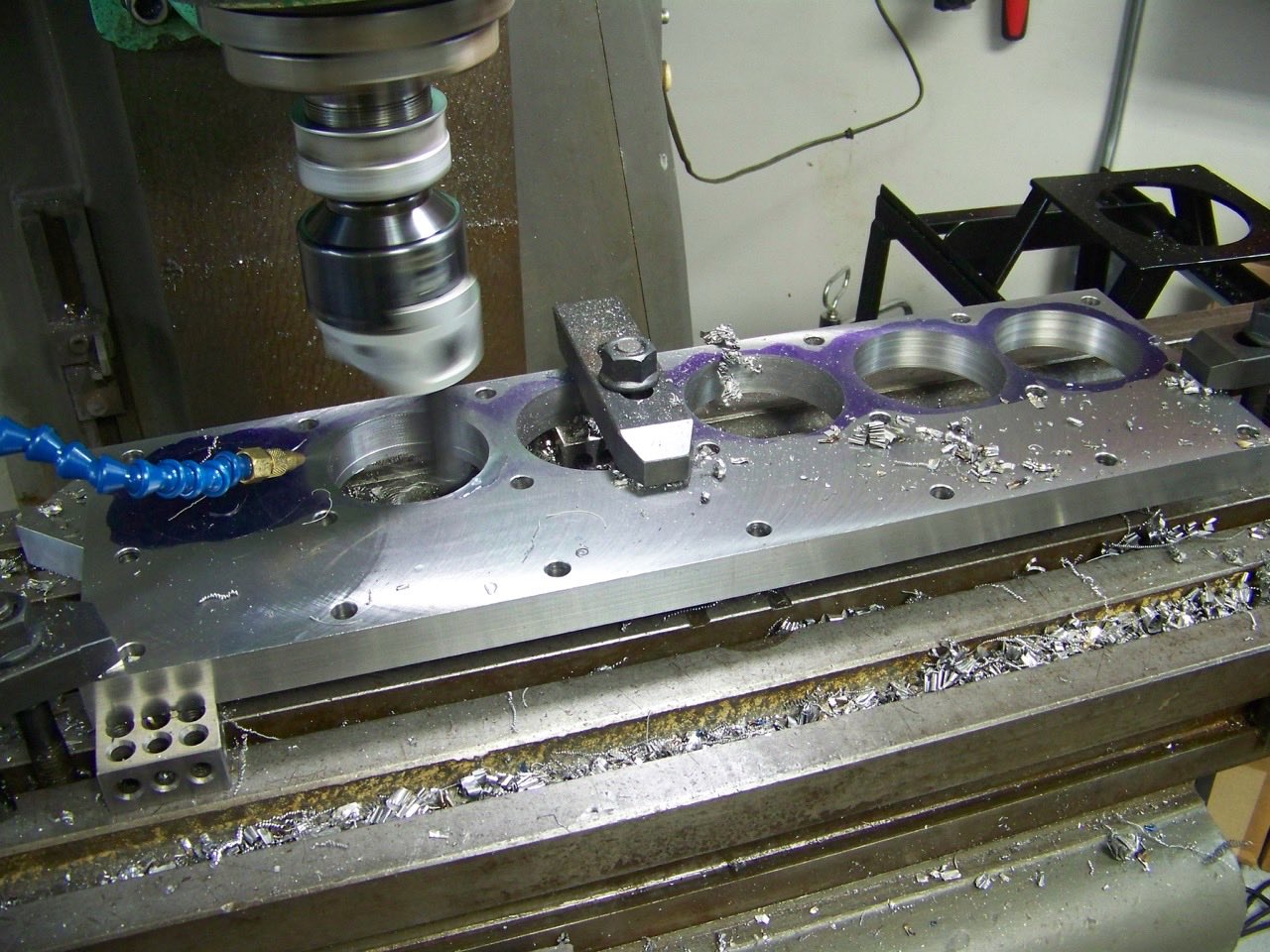
- 100_1556 (1).jpg (231.81 KiB) Viewed 9060 times
Final clean up included chamfering both ends of all holes, and milling a quarter round on the corners and all top edges (the bottom edges against the cylinder head gasket were left unmilled). Then the unmilled face of the slab was stamped "DODGE / PLYMOUTH" and the bolt holes were number stamped with the torqing order.
To prepare the cylinder block, the crankshaft bearing caps were installed and torqued to spec, the bell housing and front mount plate were installed and torqued to spec, and the engine block was mounted in a cradle on the regular mounting points. All of this was done to simulate the major stresses imposed on the block - ask any machinist who has had to level a large machine tool such as a lathe, and they will tell you that, yes, cast iron can and does "bend" and "twist" over time under pressure.
Without installing the torque plate, I then measured all of the cylinder bores (top, middle, and bottom, and parallel and perpendicular to the crankshaft axis, i.e. six different measurements for each cylinder). I used a good quality 2" - 6" range Mitutoyo dial bore gage and a 3.2503" setting ring. I'm not a fan of using outside mikes to set dial bore gages, and I found a setting ring to match the stock bore, and then compare from that diameter using the bore gage. I find this method gives me consistently better and repeatable measurements compared to snap gages or inside mikes.
The factory new specs for taper and out-of-round are a maximum of 0.001" for each measurement. Since I'll be using OEM rings, which include a chrome-faced top ring, the tolerance for taper especially is low, and the 0.001" maximum is reasonable. If I could find moly-faced rings, the tolerance would be less strict.
This block had previously been through a commercial machine shop, where the top had been decked, the crankshaft bearing bores had been line bored, the block had been Magnafluxed for cracks, and the cylinders had been bored and honed to 0.020" over stock, but all done without a torque plate as far as I know.
The measurement results are in the table below (the values in the green cells were measured, all other values calculated). Notice that all except one of the measurements (the middle out-of-round on No. 6) was within the 0.001" spec, although some just barely by a ten-thousandth. What surprised (and disappointed) me the most was the variance in total bore diameter across the six cylinders: more than 0.003"! Fortunately, the OEM aluminum pistons aren't exactly made to close tolerances either, so some mixing and matching to the individual cylinder bores will reduce those piston-to-cylinder wall clearances. I'm also having the pistons coated with an abradable powder coating, which will help to fill in some of that piston clearance.
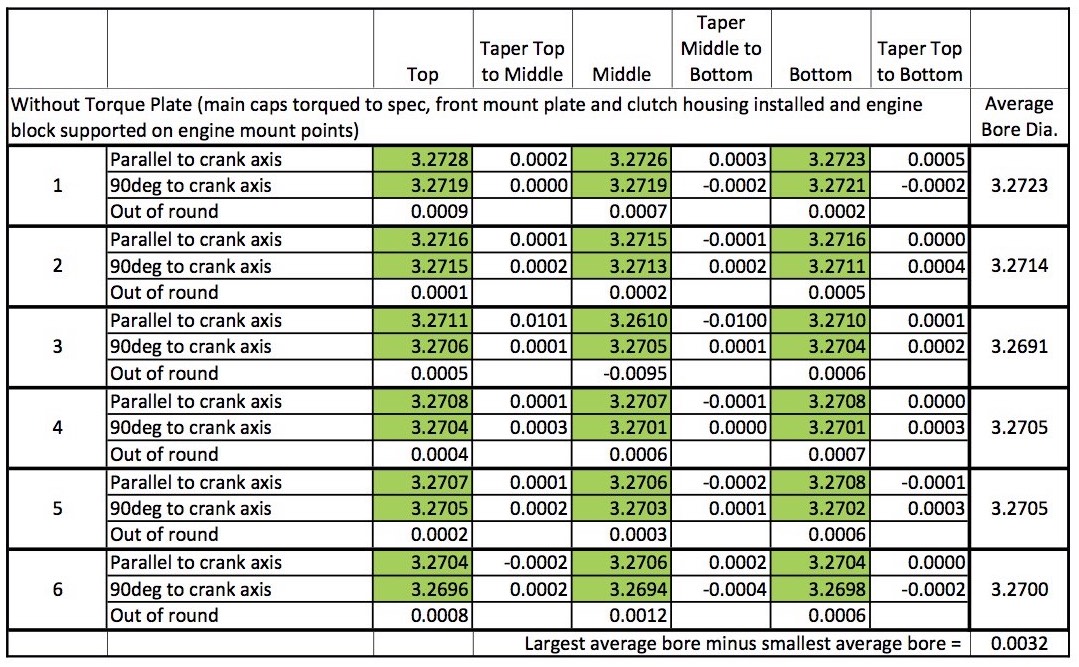
- Cylinder Bore Measurements with Torque Plate.jpg (240.27 KiB) Viewed 9060 times