 Home
Home 
I used a pair of GM truck mounts that I had laying under the bench, and they seem to have worked out nicely.
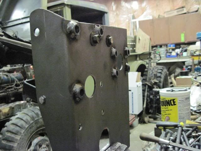
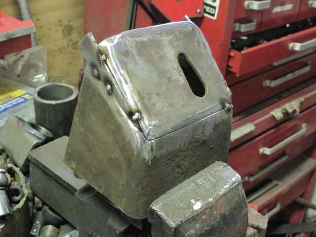
Here is the passenger side mount after the first two cuts. I didn't need the piece on the left.
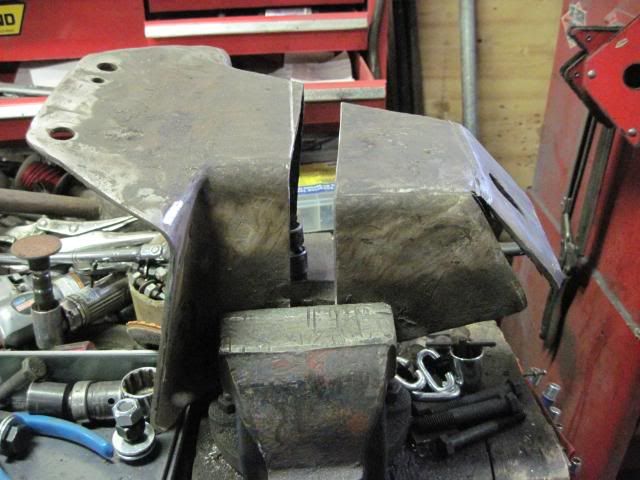
You can see where I needed to change the angle of the motor mount pad to match the Ford Block
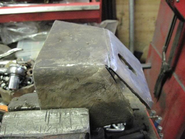
Two small inserts and the gap is filled
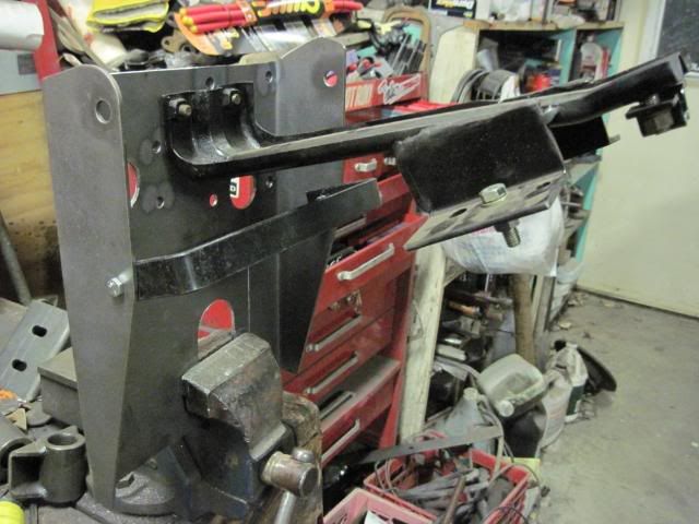
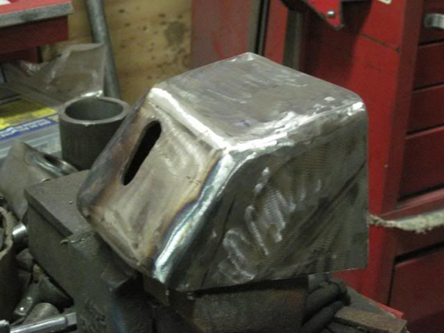
Finish welded and cleaned up, and it almost looks like a factory piece.
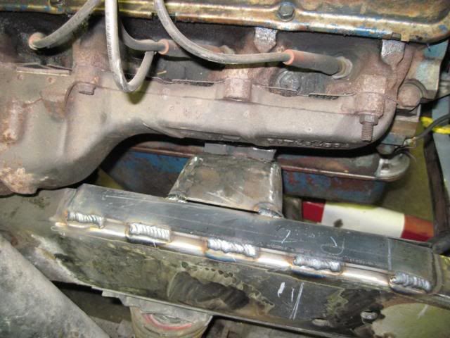
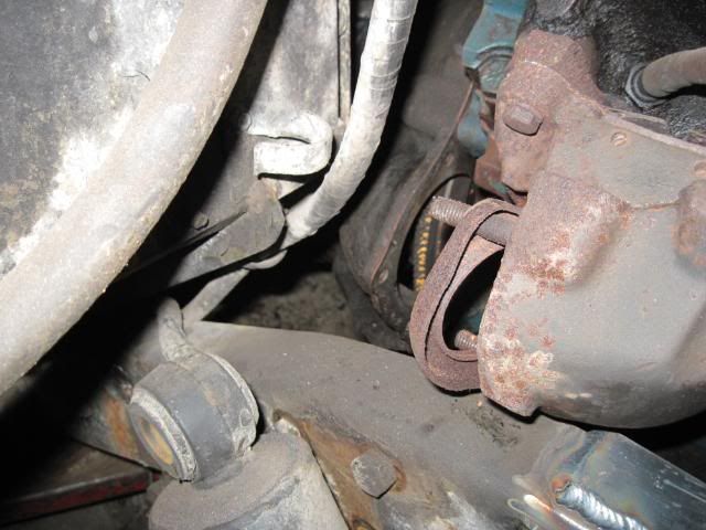
Bolted up and tacked into place.
The drivers side was basicaly a carbon copy, so I didn't take any pictures of it.
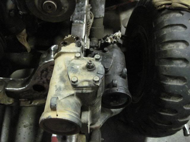
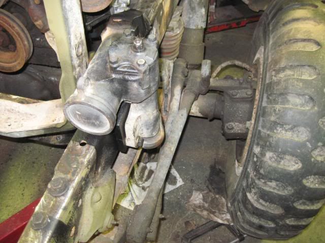
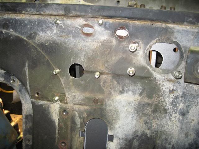
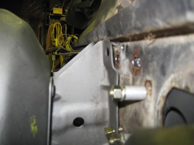
Here is a few shots around the passenger side exhaust manifold. The angle of the pictures dosen't really convey how much room is there, but I might actually be able to squeek the pipe through without too much grief.
I'm thinking a mild body lift of about 1.5 - 2" should make everything work out just fine, without generating more problems.
As for the rad, I'm going to have the lower port moved to the other side of the tank to meet up with the Ford Water pump. If I don't end up needing a body lift, I've got enough room to run a fair sized mechanical fan at the moment, and I'd like to stay away from an electric fan if at all possible.
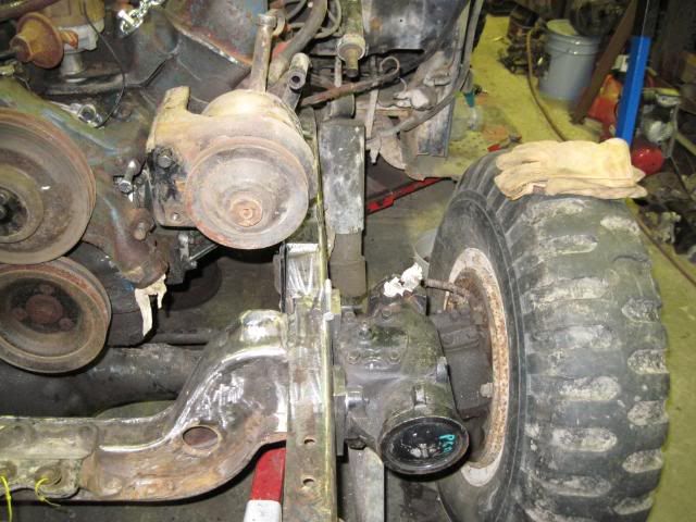
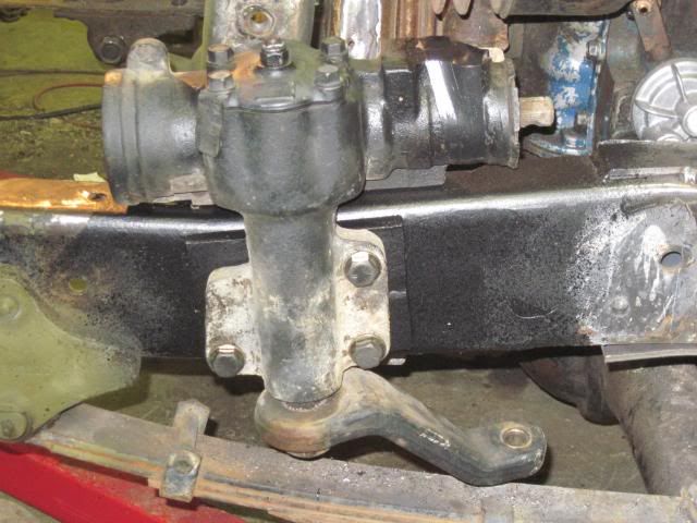
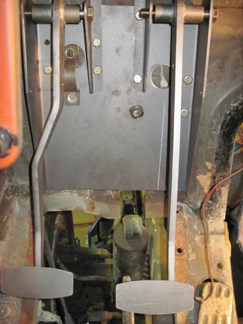
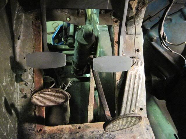
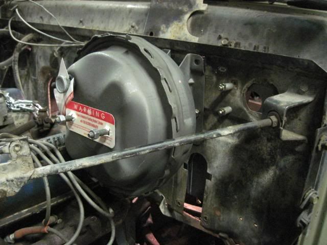
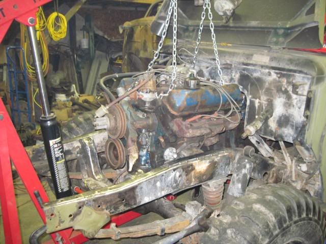
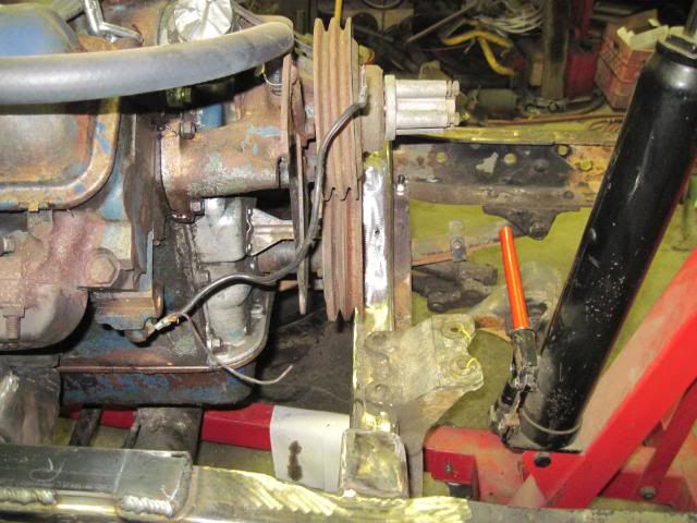
Here are some shots of various angles showing how the engine is sitting in the chassis at the moment.
The obligatory distance shot...
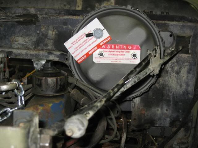
Lefts side
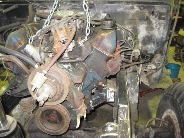
Right side
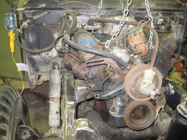
Front
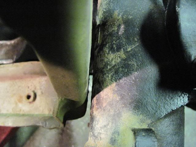
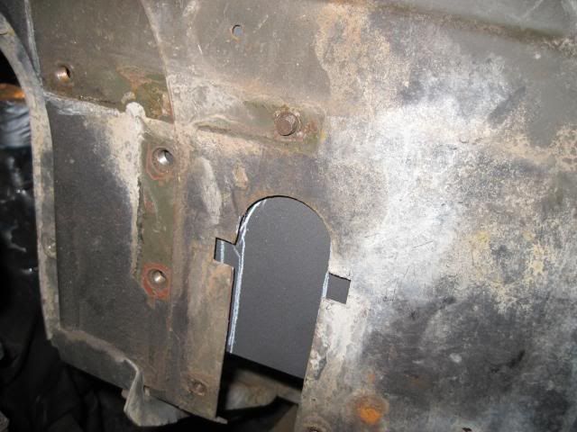
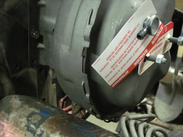
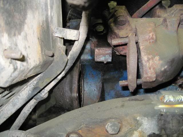
And here is my newest issue to solve....Getting the lines to the remote oil filter....
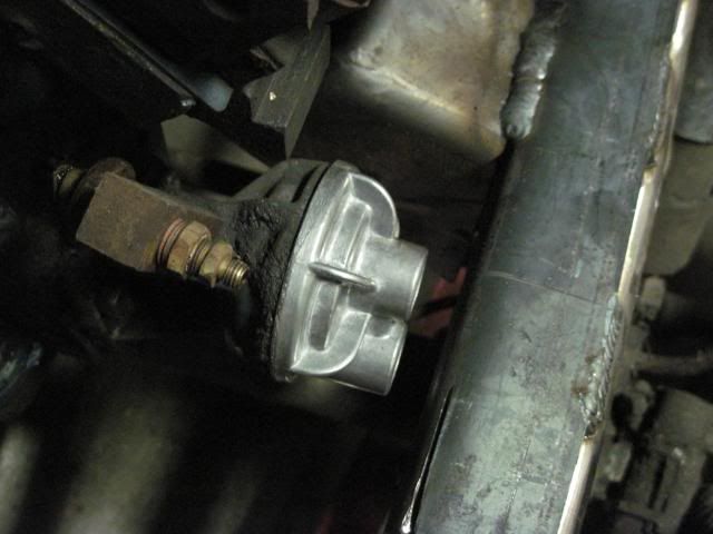
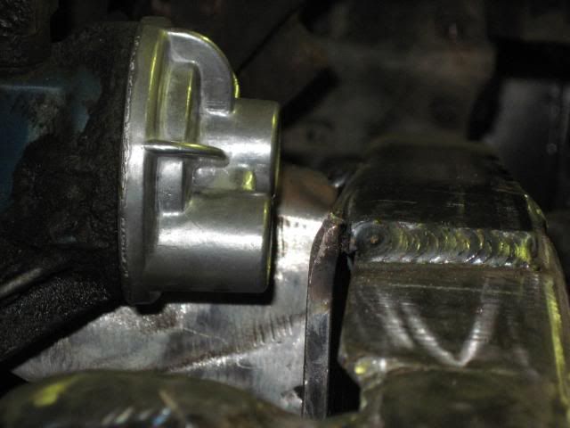
Looks like I'll need to be cutting a little of the frame after all...