 Home
Home Project: Old Guard - lots of pictures
Moderators: Cal_Gary, T. Highway, Monkey Man, robi
-
Master Yota
- MSGT

- Posts: 828
- Joined: Sun Nov 15, 2009 11:50 am
- Location: Prince George BC Canada
- Contact:

Interesting choice in power plants. The FE will work great but there are a lot of folks that would pay big bucks for that CJ 428 engine. You did get me thinking though,if I did Ford it would be the 429/460 family. Here is a photo of the last FE I built for a 64 Ford, and with the cam I chose was a real torque monster.

MY Life Past and Present
http://crayonmedia.com/wayne/
http://crayonmedia.com/wayne/
-
Master Yota
- MSGT
- Posts: 828
- Joined: Sun Nov 15, 2009 11:50 am
- Location: Prince George BC Canada
- Contact:
I chose the 428 mostly because I had it, and secondly its not much bigger dimensionally than a 350. I had a 350 in my previous M37, and loved it. My 428 makes almost double the HP and torque, and I figured that more must be better - right?
Its a reliable engine, with reasonable mileage vs. performance numbers, and its still easy enough to get parts for. They are simple to work on, and virtually bullet proof.
The dimensions were the key factory though, only an inch bigger all the way around over a SBC and only about 70# heavier. That means it weighs about as much as the 251 its replacing...
Ray
1953 CDN. M37
1954 CDN. M152
1953 CDN. M37
1954 CDN. M152
-
Master Yota
- MSGT
- Posts: 828
- Joined: Sun Nov 15, 2009 11:50 am
- Location: Prince George BC Canada
- Contact:
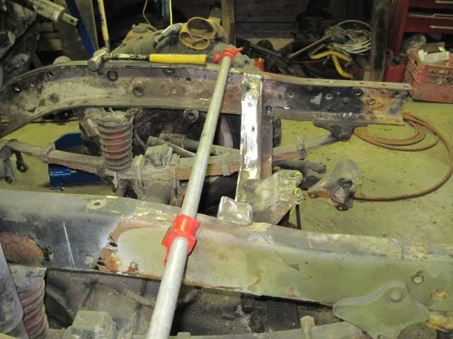
Got some work done. The crossmember mods are complete and the new shaved unit is back in the truck. Also managed to get a good start on the driver's side boxing of the frame rail.
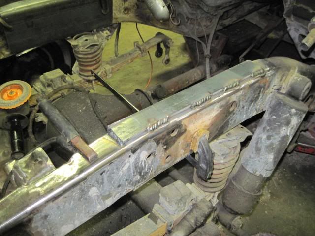
I plated the crossmember in again using 3/16's plate, formed from 3 separate pieces and fully welded. I replaced the rivets with 7/16 NF G8 bolts with stovers, so they should hold up just fine for a good long time. The top of the crossmember was welded in place originally, so I duplicated that attachment again.
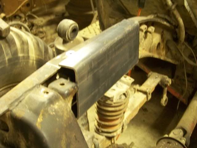
The rail boxing was accomplished with 1/4" plate formed into a channel shape to cover the top and bottom of the rails, on the outside (it fits over the rail). I'll stitch it into place, on both sides, and it should be more than enough to hold the engine in place.
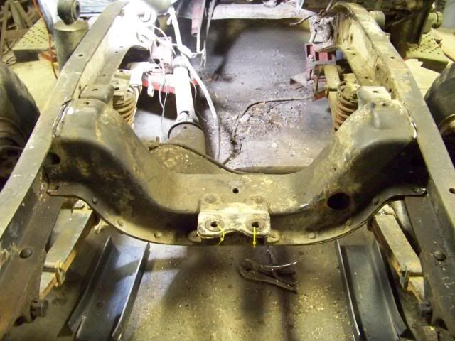
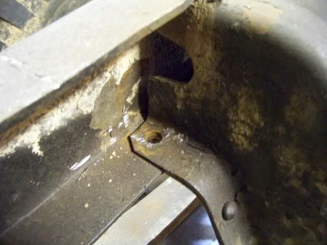
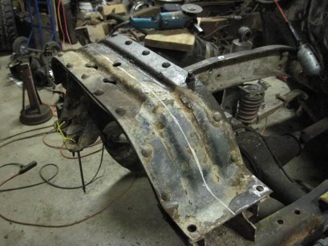
Here is the factory crossmember:
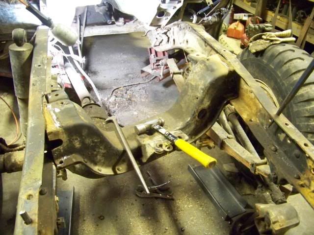
Cutting welds
Removing more rivets
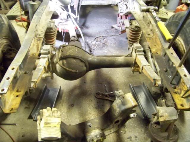
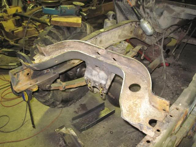
Some BFH work to get it out
And it on the floor - I did measure the rails for spread, and it was minimal - about 3/4" in total.
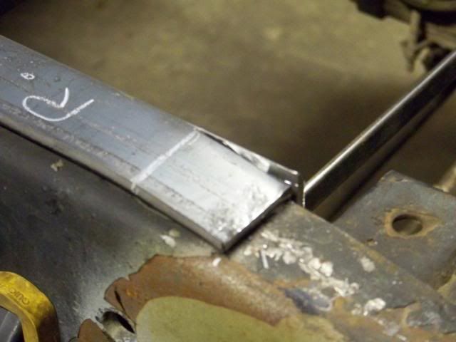
Here you can see the cut lines - A small square and a piece of chalk was all I used to lay out the lines.
Top side
Bottom side
Severed in half! A 5" grinder with a zip cut makes quick and accurate cuts for this type of job.
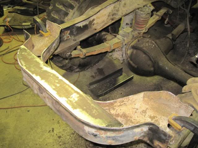
The lower plate insert. I don't have any pictures of the two upper-side plates, but I just used the crossmember as a pattern and cut out each side from the scrap I had left over.
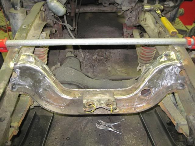
After it was fully welded and cleaned up, the bar clamp easily pulled the rails back into position, and once the member was loosely bolted in place, I set the distance between the rails and welded the top side. Afterwards the bolts where snugged up and the crossmember was considered finished.
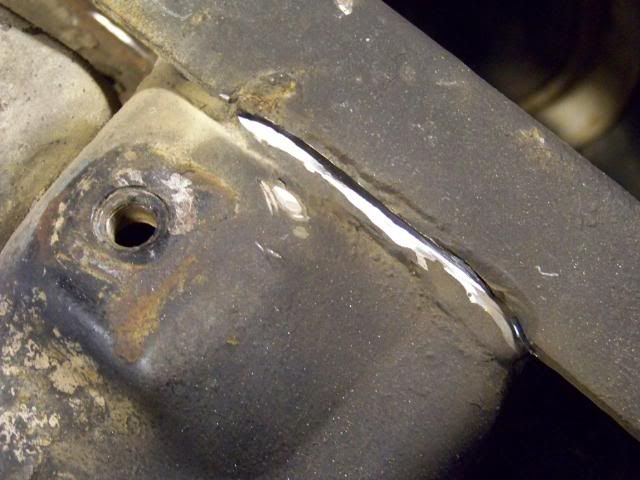
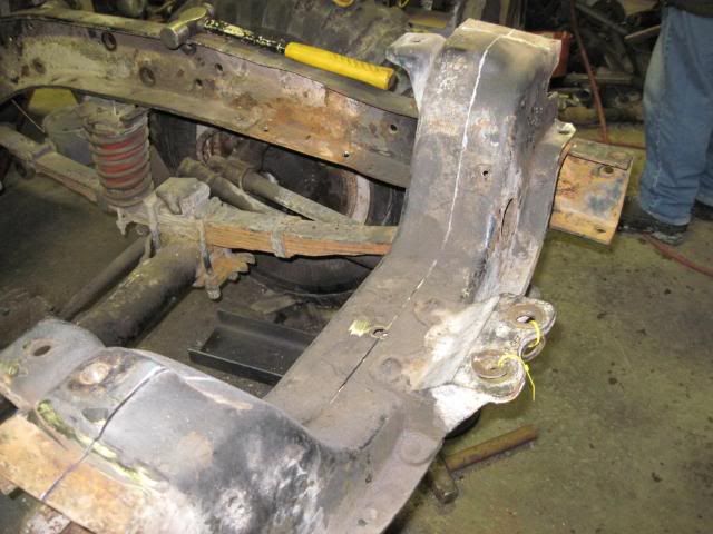
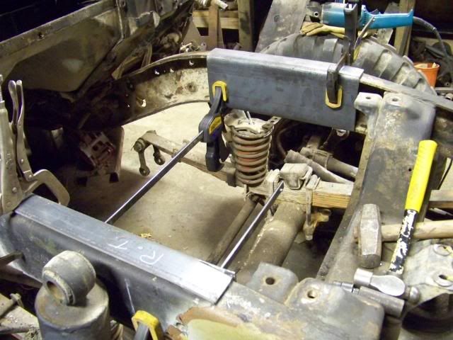
Here are some shots of the Frame Rail boxing - which will provide a home for the new engine mounts.
There are some dips in the frame, so some relief cuts needed to be made so that the steel could be formed into place with a BFH.
After some adjustments
Stiched into place - on the top left side
Hopefully I'll get some more accomplished this week...
I plated the crossmember in again using 3/16's plate, formed from 3 separate pieces and fully welded. I replaced the rivets with 7/16 NF G8 bolts with stovers, so they should hold up just fine for a good long time. The top of the crossmember was welded in place originally, so I duplicated that attachment again.
The rail boxing was accomplished with 1/4" plate formed into a channel shape to cover the top and bottom of the rails, on the outside (it fits over the rail). I'll stitch it into place, on both sides, and it should be more than enough to hold the engine in place.
Here is the factory crossmember:
Cutting welds
Removing more rivets
Some BFH work to get it out
And it on the floor - I did measure the rails for spread, and it was minimal - about 3/4" in total.
Here you can see the cut lines - A small square and a piece of chalk was all I used to lay out the lines.
Top side
Bottom side
Severed in half! A 5" grinder with a zip cut makes quick and accurate cuts for this type of job.
The lower plate insert. I don't have any pictures of the two upper-side plates, but I just used the crossmember as a pattern and cut out each side from the scrap I had left over.
After it was fully welded and cleaned up, the bar clamp easily pulled the rails back into position, and once the member was loosely bolted in place, I set the distance between the rails and welded the top side. Afterwards the bolts where snugged up and the crossmember was considered finished.
Here are some shots of the Frame Rail boxing - which will provide a home for the new engine mounts.
There are some dips in the frame, so some relief cuts needed to be made so that the steel could be formed into place with a BFH.
After some adjustments
Stiched into place - on the top left side
Hopefully I'll get some more accomplished this week...
Ray
1953 CDN. M37
1954 CDN. M152
1953 CDN. M37
1954 CDN. M152


U Been Busy
Looking real sharp too, Master Yota.
Bruce,
1953 M-37 w/ow
Retired Again
Keep Em Rollin'
VMVA
1953 M-37 w/ow
Retired Again
Keep Em Rollin'
VMVA

Transfer Case Stuff
Ray, I'm still working on that cd for more info/tool stuff. I forgot to mention that before.
Regards,
Regards,
Bruce,
1953 M-37 w/ow
Retired Again
Keep Em Rollin'
VMVA
1953 M-37 w/ow
Retired Again
Keep Em Rollin'
VMVA

-
Master Yota
- MSGT
- Posts: 828
- Joined: Sun Nov 15, 2009 11:50 am
- Location: Prince George BC Canada
- Contact:
The mods to the front brace are to accomodate the swing of the draglink when I put the crossover steering in. The oilpan should clear just fine as its a rear sump unit.Josh wrote:Ray, why did you take the front brace out instead of reshaping the oilpan? Just asking, not being critical.
Josh
Even if given a choice in your scenario, I would still mod the crossmember over the oil pan, as the CM dosen't have anything to leak out of it...
Ray
1953 CDN. M37
1954 CDN. M152
1953 CDN. M37
1954 CDN. M152

Looks good. Nice to see another CDN M-37. I could use the engine for mine. Mine needs to be rebuilt and my spare also needs to be rebuilt. I was going to combine the two of them. If yours is a runner than that would get me back on the road for now. Drop me a line and let me know how much and stuff. I could use a bunch of the other bits also.(steering box, trany, PTO, transfer case and drive shafts) I'm down in Vancouver so it would be a bit of a drive to come get it.
1952 cdnM37
-
Master Yota
- MSGT
- Posts: 828
- Joined: Sun Nov 15, 2009 11:50 am
- Location: Prince George BC Canada
- Contact:
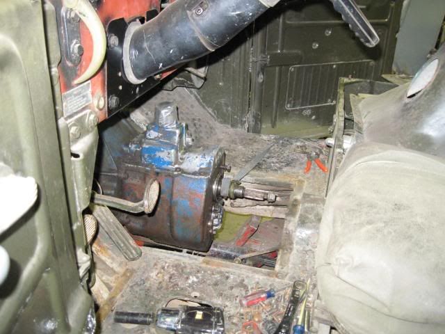
Slipped the BBF between the rails on tuesday night. No mounts yet, but at least I have an idea of how its going to fit and what some of the issues might be.
428 and NP435 up in the air and heading for the new home
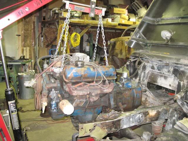
Pretty good fit so far...
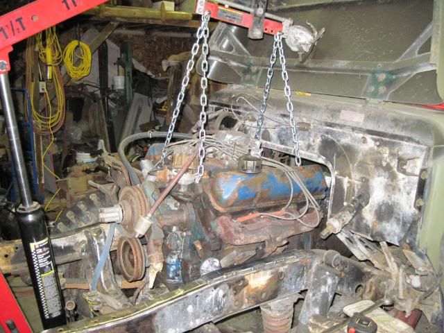
Enough fire wall clearance to keep things happy
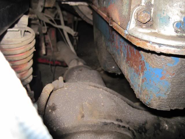
Should be enough clearance at the diff too, as the D60 is shaped differently
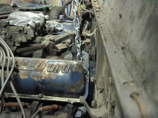
The exhaust manifold on the passenger side could cause problems. Nobody makes a center dump header either...
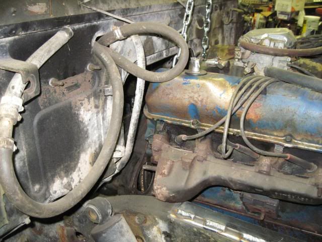
The pass. side exhaust manifold prevents me from lowering the engine any futher between the rails. Looks like some major floor surgery might be needed if I can't find another solution.
I'm leaning towards a mild body lift to generate the floor clearance I need and put some space between the exhaust and the body.
428 and NP435 up in the air and heading for the new home
Pretty good fit so far...
Enough fire wall clearance to keep things happy
Should be enough clearance at the diff too, as the D60 is shaped differently
The exhaust manifold on the passenger side could cause problems. Nobody makes a center dump header either...
The pass. side exhaust manifold prevents me from lowering the engine any futher between the rails. Looks like some major floor surgery might be needed if I can't find another solution.
I'm leaning towards a mild body lift to generate the floor clearance I need and put some space between the exhaust and the body.
Ray
1953 CDN. M37
1954 CDN. M152
1953 CDN. M37
1954 CDN. M152
-
chris olson
- PFC

- Posts: 74
- Joined: Fri Mar 20, 2009 4:16 pm
- Location: Burnaby BC
headers
Looks like those manifolds are going to be a pain
Might be time for a header kit...
http://www.speedwaymotors.com/429-460-B ... 37279.html
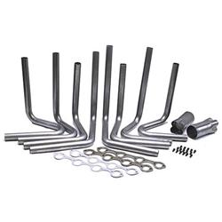
Might be time for a header kit...
http://www.speedwaymotors.com/429-460-B ... 37279.html
1952 M37cdn
looks like it fits pretty well. You're correct on the Dana diff, you'll be fine. That is one thing Ford has always been smart about Vs. GM and Chrysler is ALWAYS putting the dizzy up front. The other two never figured that out with their small blocks. I know it sure helped when I was getting the 400 in position as opposed to the 360.
I'd advise against the body lift, as it will look OK everywhere except dead on in the front. the way the sheetmetal comes right down to the frame will be a tough gap to fill. Have you tried flipping the manifolds over, so the exhaust faces forward... would make for a somewhat convoluted escape from the engine bay, but, it would be better than cutting the floor and frame. Contrary to what most people on here think, I actually dont like cutting on the original structure, I only resort to it if all else fails.
A header kit would also work, as Chris pointed out.
Lastly, you could always route the exhaust outboard of the frame, rather than trying to tuck it back in as it comes down.
